What about the part of the real world that we cannot see? In computer graphics, this is eliminated through a technique called clipping.
Essentially, we need to worry about clipping three different entities:
1) lines
2) polygons
3) text
Windows are usually expressed using the following specifications:
(1) Xmin (2) Xmax (3) Ymin (4) Ymax
It is very important to note the following: "window coordinates" means "user coordinates" means "world coordinates".
Much of the time the window is displayed on the entire screen. If we are using just a portion of the screen, then the rectangular area that is occupied by the window is called the viewport. It is important to note here that coordinates for specifying the viewport are independent of the coordinates for specifying the window.
When we talk about specifying coordinates, there are two methods normally used:
1) absolute device coordinates
2) normalized device coordinates
Preferred method is normalized coordinates which means that X and Y values will fall in the range of [0,1].
Look at figures 4.2 and 4.3 on pp.120 & 121.
A window-to-viewport transformation is done by mapping a window onto a specified viewport. We can specifiy commands for a window and a viewport as follows:
set_window(Wxl,Wxh,Wyl,Wyh) where:
Wxl - is window X-low
Wxh - is window X-right
Wyl - is window Y-low
Wyh - is window Y-high
The viewport is specified in the same way:
set_viewport(Vxl,Vxh,Vyl,Vyh)
In most graphics systems, the viewport is that area of the output device (such as the display screen) onto which the window is mapped. So as an example, let's specify viewport coordinates (.6,1,.5,1) and window coordinates (0,25,-4,22):
set_window(0,25,-4,22);
set_viewport(0.6,1.0,0.5,1.0);
Then if we drew the following house:
draw_line(10,10,15,16);
draw_line(15,16,20,10);
draw_line(20,10,20,0);
draw_line(20,0,10,0);
draw_line(10,0,10,10);
That would produce Figure 4.4 on page 121.
Window-toViewport Transformation
Note1: Every line that we wish to display must at some point in time be drawn in absolute screen coordinates.
Note2: If we specify an image in normalized device coordinates, this can be converted into absolute device coordinateswith little or no trouble.
That is, "user coordinates"->"normalized coordinates"->"absolute coordinates"
Note3: Typically, we specify a viewport to be smaller than the actual display. Why might we want to do this? Problem: Draw the following setup:
set_window(0,25,-4,22);
set_viewport(0.6,1.0,0.5,1.0);
As we mentioned earlier, many times we would like to transform a coordinate system into a normalized coordinate system. As an example, let's suppose we wanted to transform the user coordinate system into a normalized coordinate system. >In particular, what would it take to transform a point from the user coordinate systems to the normalized coordinate system assuming a user point of (Xuser,Yuser) and a normalized point of (Xnorm,Ynorm). The following equations will take care of this problem for us:
Xnorm=(Xuser-Wxl)/(Wxh-Wxl)*(Vxh-Vxl)+Vxl
Ynorm=(Yuser-Wyl)/(Wyh-Wyl)*(Vyh-Vyl)+Vyl
Note: This equation does not do any error checking. That is, if a point is outside the window, the equation will convert that point (incorrectly) anyway. To avoid this problem, what needs to happen?
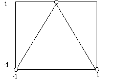
Problem: Define a triangle in world coordinated where -1<=X<=1 and -1<=y<=1. Transform the points of the triangle into normalized viewport coordinates. Part A: Assume the viewport is the entire display screen. Part B: Assume that the viewport is the bottom left quarter of the display screen. The following picture represents the triangle as it is to be transformed:

Just as a side note, as soon at the window and viewport specifications are made, we can do some simplification to the above equations as follows:

A similar simplification for the Ynorm equation can be followed.
The classic clipping algorithm is credited to Cohen-Sutherland. We will limit clipping in this instance to straight lines.
The algorithm first establishes nine regions of the two-dimensional plane as follows:
	1001|0001|0101
	--------------
	1000|0000|0100
	--------------
	1010|0010|0110
A single point in the two-dimensional region has a region code in the order 3 2 1 0 as follows:
1) Bit 3 => left boundary and is a 1 if the point is left of the left boundary.
2) Bit 2 => right boundary and is a 1 if the point is right of the right boundary.
3) Bit 1 => bottom boundary and is a 1 if the point is below the bottom boundary.
1) Bit 0 => top boundary and is a 1 if the point is above the top boundary.
Therefore to clip a straight line we proceed as follows:
1) Assign each endpoint of the line segment an associated region code.
2) Logically OR both regions.
3) If the result=0000, then no clipping is required because the line segment is entirely within the visible region
4) Else logically AND both regions and if this result is <> 0000, then we can trivally reject because the entire line segment is outside the visible region.
5) If case 3 and 4 are both false, then this is a nontrivial case that must be handled.
Nontrivial cases are as follows:

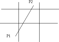
Note: In this particular case, both endpoints are not outside the same boundary and both endpoints are not inside the visible boundary; therefore, this line needs to be clipped. In this particular case, we need some uniform clipping method so we choose to clip the line in a 3 2 1 0 (left, right, bottom, top) manner.
Show pictorially what this would look like.
The Cohen-Sutherland clipping algorithm is on pp.129-130 and is there for your reading enjoyment!!